XOrduino: Difference between revisions
Tonyforster (talk | contribs) |
No edit summary |
||
| Line 1: | Line 1: | ||
=Background= |
=Background= |
||
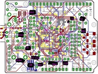
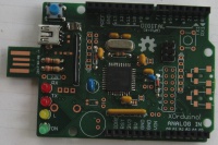
The XOrduino and [[XO Stick]] are [http://arduino.cc/en/ Arduino] compatible single board computers. A blank circuit board for each is included with every XO-4 computer. These boards can be populated with inexpensive (US$5 approximately) components. Some soldering skills are required, the XOstick is recommended for beginners because it has no surface mount components. |
The XOrduino and [[XO Stick]] are [http://arduino.cc/en/ Arduino] compatible single board computers. A blank circuit board for each is included with every XO-4 touchscreen computer. These boards can be populated with inexpensive (US$5 approximately) components. Some soldering skills are required, the XOstick is recommended for beginners because it has no surface mount components. |
||
The boards can be used in robotics experiments in two ways: |
The boards can be used in robotics experiments in two ways: |
||
Revision as of 22:27, 19 March 2013
Background
The XOrduino and XO Stick are Arduino compatible single board computers. A blank circuit board for each is included with every XO-4 touchscreen computer. These boards can be populated with inexpensive (US$5 approximately) components. Some soldering skills are required, the XOstick is recommended for beginners because it has no surface mount components.
The boards can be used in robotics experiments in two ways:
- Install the Arduino IDE in Gnome or Terminal and use it to program the Arduinos as stand alone robotics experiments
- Load the Arduino with Firmata software (once only using the Arduino IDE) and use the Arduino as an Input/Output board for Turtle Art
Assembly notes
See C. Scott's notes below.
For folks assembling A1 boards, the PDF links on http://cananian.livejournal.com/tag/xorduino are useful.
The following components are polarised, they must be fitted the right way
- U1, U8 - align the dot with the silk screen
- RN1 - pin 1 has a dot which aligns with the number 1 on the silk screen
- D1, D2 - the bands match the silk screen
- The LEDS have a flat side which matches the silk screen, the lead on that side is shorter, the yellow LED has a shorter lead where its flat side would be.
- Though the silk screen shows a polarised electrolytic capacitor for C8, the parts list specifies a small blue ceramic capacitor which can be mounted either way.
The USB connector mounts on the board top despite the silk screen showing it under, the only bottom side component is the U8 op amp.
If you do not want the Scratchboard features omit U7, U8, U9, R7, RN1, RN3, C5, C7, C10, C11, C13, JP6, S2 If you chose to load op amp U8 (to get the Scratchboard features) you need to break jumper JP5 which is next to U8 on the underside.
Soldering the surface mount devices is difficult
- read the soldering tutorial
- have a small tip on the iron, if damaged buy a new one
- use thin solder
- have good lighting
- use solder wick to remove solder bridges between adjacent pins, (but avoid dragging the wick across the pads or they may break)
Extra information for component placement:
Programming
With just the chip mounted, the following command should work as a smoke test:
avrdude -c usbtiny -patmega32u4 -U flash:r:test.hex
(Do this as root if you must, then see XO Stick for how to fix this.)
See XOrduino/bootloader for using another Arduino as a programmer
Once the crystal, 18pF capacitors, and USB components are mounted, install the arduino bootloader by:
- opening the arduino IDE
- selecting "USBtinyISP" under Tools > Programmer *
- selecting "Arduino Leonardo" under Tools > Board
- selecting Tools > Burn Bootloader (this takes a while. watch the status line in the arduino IDE)
- Note "USBtinyISP" if using a USBtiny programmer or "Arduino as ISP" if using another Arduino as programmer
C. Scott's notes
Notes on XOrduino v4 boards:
- avoid tab on usb connector, move to body
- N/C jumpers turned out N/O (scratch sensor board)
.- merge 5V and +5V nets
- C5/C7 too close together (and too close to C9) & need polarity marks
- C11/C13 needs polarity mark (or to be unpolarized)
- flip RN3?
- audio jack footprints are wrong.  and drill holes overlap for top&bottom
- just use tip and sleeve(gnd) on audio jack (leave ring(s) disconnected)
  use 1/8" instead of 3/32"?
  digikey CP1-3523N-ND $0.39480 qty 100 (stereo, no switch)
- right angle pot is right but don't need strain relief holes, need knob (shorter handle?)
.- mini USB jack silkscreen on wrong side .- mini USB just a tiny bit too close to pcb plug
- mounting hole clearances too small:

- add front nose skid (near where audio jack currently sits?)
- potentiometer footprint
- add light sensors and/or bumper switches somehow
  light sensors pointed at the wheels?
- add labels to new arduino 1.0 pins (SCL/SDA above AREF)
- add breakoff tabs to thicken USB plug (by reset pin, two deep)
- solder spot under AVR is unnecessary
- male header strip should be female for arduino headers
  1x S7004-ND (6 pin)
  2x S4008-ND (non-stock) or S7006-ND (8 pin)
  1x S7043-ND (10 pin) or S7008-ND (should be cheaper, but isn't)
- ISP header needs pin 1 indication, label.
- Yellow LEDs don't have a flat side!
- add LED polarity silkscreen
- remove solder mask on solder jumper center
- replace 2x7 shorting header w/ 1x7 signal header and array of
  shorting jumpers
NOTE THAT ATmega32u4 should be placed upside down. (rotate it?)
TESTED: xorduino can be programmed w/ nothing mounted but the chip and the ISP header.
Distribution
1. cjb
2. cscott (cannibalized)
4. Quozl
5. Mike Lee
6. Pippin Wallace
7. Pippin Wallace
8. Sridhar Dhanapalan
9. Tony Forster
10. Javier Andres Galaz Jeria
11. Alan Jhonn Aguiar Schwyn
12. Stephen Thomas
13. Ricardo Moran
14. George Hunt
15. Juan Cubillo
Sources
http://github.com/cscott/xorduino -- look at the "A1" tag for the schematics for the A1 boards. Latest XOrduino is at HEAD, targetted for the B1 build.
See also
Links
http://arduino.cc/en/Tutorial/ArduinoISP programming the bootloader with another Arduino
https://www.sparkfun.com/products/9825 pocket programmer
https://github.com/cscott/xorduino circuit board artwork, etc current revision
https://github.com/cscott/xorduino/tree/A1 circuit board etc A1 revision
https://github.com/cscott/xorduino/blob/A1/XOrduino-sch.pdf?raw=true schematic A1
https://github.com/cscott/xorduino/blob/A1/XOrduino-brd.pdf?raw=true circuit board A1
https://groups.google.com/forum/?hl=en&fromgroups#!forum/xorduino Google interest group
http://cananian.livejournal.com/66129.html and http://cananian.livejournal.com/66654.html blog
http://www.sparkfun.com/tutorials/106 a soldering tutorial
http://www.atmel.com/devices/atmega32u4.aspx?tab=documents Documentation ATmega32U4
https://plus.google.com/photos/109541946294746531763/albums/5772322118805954321 photos

