File list
This special page shows all uploaded files.
| Date | Name | Thumbnail | Size | Description | Versions |
|---|---|---|---|---|---|
| 11:02, 2 August 2007 | XS server stable.repo.txt (file) | 1 KB | The yum configuration file for the school server stable repositories | 1 | |
| 11:03, 2 August 2007 | Testing.repo.txt (file) | 2 KB | The yum configuration file for the school server stable repositories | 1 | |
| 14:38, 16 June 2008 | XS Network SwitchTest.png (file) |  |
11 KB | 1 | |
| 01:12, 12 October 2007 | B4Suspend1835III.png (file) |  |
11 KB | 1 | |
| 05:48, 2 January 2008 | Read-tinderbox.py (file) | 11 KB | Python script for reading the tinderbox measurements | 1 | |
| 03:23, 13 October 2007 | B4Suspend1835II.png (file) |  |
12 KB | 1 | |
| 00:53, 13 October 2010 | XO1.75 EC Breadboard Wiring.xls (file) | 13 KB | Fixed layout when printed | 2 | |
| 02:30, 23 June 2009 | XO 1.5 EC Power Sequence A1.pdf (file) | 14 KB | 1 | ||
| 15:26, 16 June 2008 | XS Network ServerTest.png (file) |  |
14 KB | 2 | |
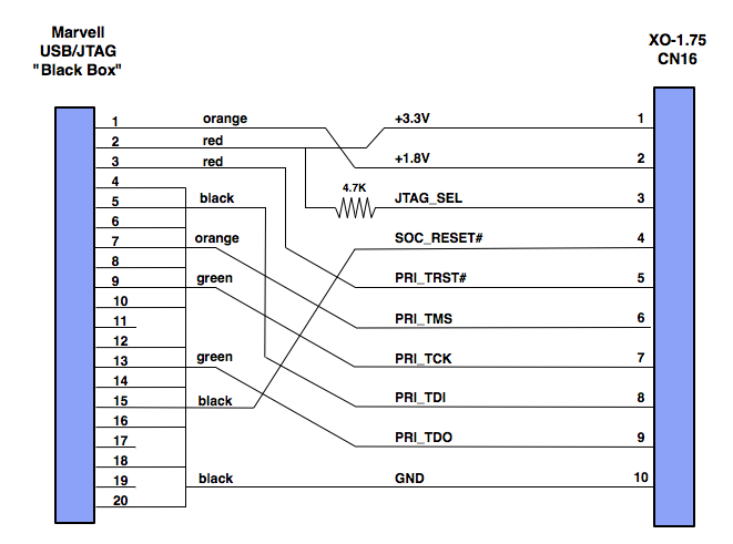
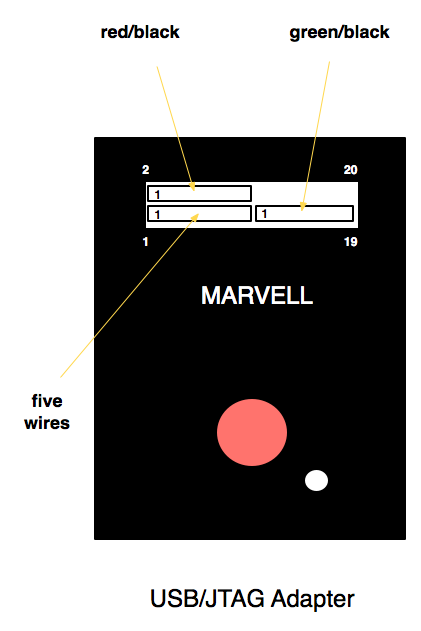
| 00:34, 17 May 2012 | XO 1.75 JTAG Cable.pdf (file) | 17 KB | Wiring of cable between Marvell USB/JTAG Adapter and a XO-1.75 laptop. PNG version Category:Hardware Category:XO-1.75 | 1 | |
| 10:56, 18 March 2008 | PeabodyAnnex.png (file) |  |
19 KB | 2 | |
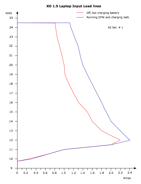
| 23:34, 10 November 2009 | CL1B A2 LoadLine.pdf (file) | 19 KB | DC power input load line of an XO-1.5 A2 prototype. This is not final, and is given only as an early example. | 1 | |
| 23:08, 10 November 2009 | CL1B B2 LoadLine.pdf (file) | 21 KB | DC power input load line of an XO-1.5 B1 prototype with the proposed power ECO. This is not final, and is given only as an early example. | 1 | |
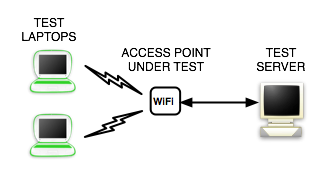
| 14:41, 16 June 2008 | XS Network AccessPointTest.png (file) |  |
21 KB | 1 | |
| 00:16, 12 October 2007 | B4SuspendECRChecklist.pdf (file) | 22 KB | 1 | ||
| 19:37, 23 April 2011 | DC Input BruteForce.png (file) |  |
22 KB | 1 | |
| 19:50, 23 April 2011 | DC Input propB.png (file) |  |
25 KB | 1 | |
| 16:37, 9 September 2013 | XO-4 FCC RF Safety Insert.pdf (file) | 27 KB | 1 | ||
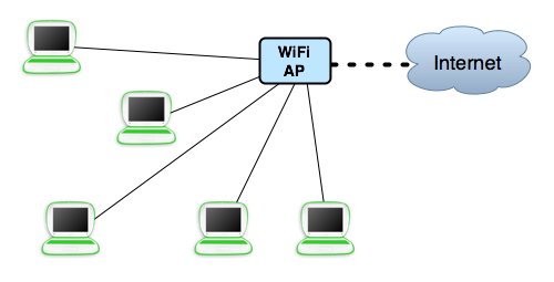
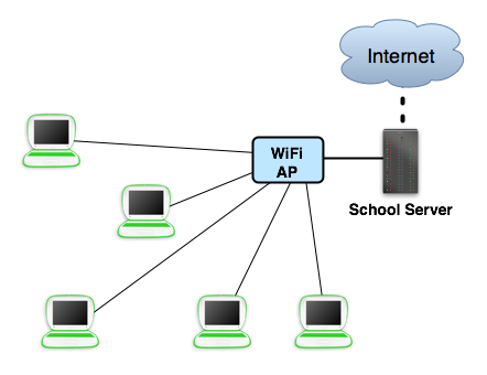
| 11:30, 14 May 2008 | Scenario simple wifi.png (file) |  |
28 KB | 1 | |
| 02:20, 23 June 2009 | XO 1.5 Connectors A1.pdf (file) | 31 KB | 1 | ||
| 05:06, 11 December 2011 | XO 3 Connectors A1.pdf (file) | 32 KB | Oops, forgot to label the Touchscreen connector | 2 | |
| 03:03, 6 September 2009 | XO 1.5 Connectors B2.pdf (file) | 33 KB | Connectors and jumpers on the XO-1.5 B1.B2 prototypes | 1 | |
| 00:12, 23 August 2008 | Speak-8.xo (file) | 33 KB | 1 | ||
| 11:31, 14 May 2008 | Scenario xs wifi.png (file) |  |
33 KB | 1 | |
| 01:33, 27 July 2009 | XO 1.5 Connectors A2.pdf (file) | 33 KB | XO 1.5 A2 prototype connectors and jumpers. These are not the same as used for production !! | 1 | |
| 00:42, 17 May 2012 | XO 1.75 JTAG Usage.png (file) |  |
34 KB | Connection of cable from XO-1.75's JTAG interface and the Marvell USB/JTAG Adapter]] PDF version Category:Hardware Category:XO-1.75 | 1 |
| 04:59, 19 May 2010 | Keyboard spanish normal.pdf (file) | 35 KB | Changed size of euro symbol, pipe symbol | 3 | |
| 03:06, 6 September 2009 | XO 1.5 EC Pinout v12.pdf (file) | 35 KB | 1 | ||
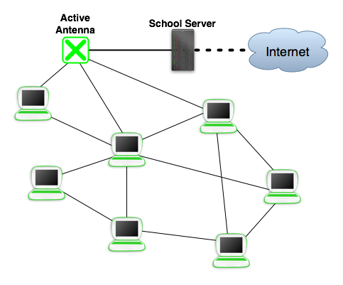
| 11:21, 14 May 2008 | Scenario simple mesh.png (file) |  |
35 KB | 1 | |
| 02:26, 23 June 2009 | XO 1.5 EC Pinout v11.pdf (file) | 35 KB | 1 | ||
| 01:27, 14 November 2009 | XO 1.5 EC Pinout v14.pdf (file) | 35 KB | GPIO mapping (version 14) for the Embedded Controller of the XO-1.5 laptop | 1 | |
| 00:06, 27 May 2010 | PixelLayoutStandard.png (file) | 35 KB | This shows the pixel layout of a typical LCD display, and its mapping to frame buffer pixels. {{PD}} | 1 | |
| 23:55, 6 July 2011 | XO3 Battery Basic.png (file) |  |
37 KB | 1 | |
| 05:01, 19 May 2010 | Keyboard english normal.pdf (file) | 38 KB | Changed size of parentheses, euro symbol | 3 | |
| 22:40, 17 January 2010 | XO 1.5 Connectors C1.pdf (file) | 39 KB | Connectors and Jumpers on a XO-1.5 C1 version motherboard. Category:XO-1.5 Category:Hardware {{CC-BY-SA}} | 1 | |
| 23:57, 12 October 2010 | XO1.75 EC Breadboard Block.pdf (file) | 40 KB | Block diagram of XO-1.75 Embedded controller breadboard. {{CC}} | 1 | |
| 22:53, 10 November 2009 | CL1B A2 LoadLine.png (file) |  |
40 KB | DC power input load line of an XO-1.5 A2 prototype. This is not final, and is given only as an early example. | 1 |
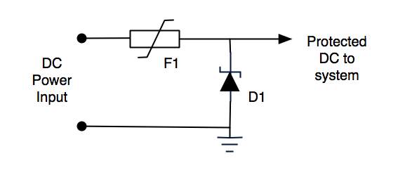
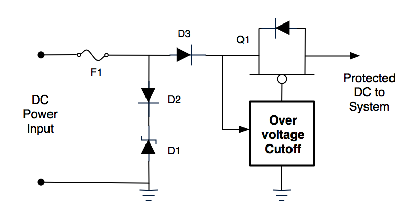
| 19:39, 23 April 2011 | DC Input XO-1.png (file) |  |
42 KB | Simplified schematic of the protection circuitry of the XO-1/1.5's DC power input. | 1 |
| 03:51, 9 January 2011 | XO 1.75 Connectors A2.pdf (file) | 43 KB | 1 | ||
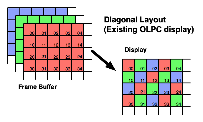
| 00:04, 27 May 2010 | PixelLayoutDiagonal.png (file) | 45 KB | This shows the pixel layout in the OLPC XO display, and how pixels in the frame buffer are mapped to it. {{PD}} | 1 | |
| 20:08, 28 September 2012 | XO 4 Power Distribution.pdf (file) | 45 KB | Minor label changes | 2 | |
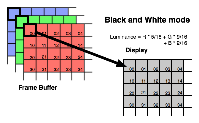
| 00:08, 27 May 2010 | PixelProcBW.png (file) | 46 KB | This shows the mapping from frame buffer pixels to OLPC display pixels with the DCON in monochrome mode. | 1 | |
| 23:06, 10 November 2009 | CL1B B2 LoadLine.png (file) |  |
48 KB | DC power input load line of an XO-1.5 B1 prototype with the proposed power ECO. This is not final, and is given only as an early example. | 1 |
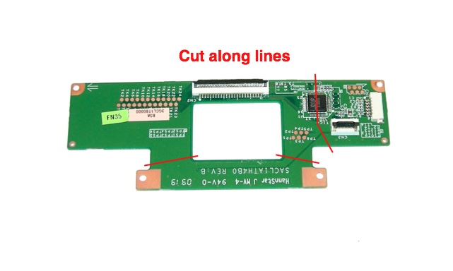
| 10:21, 2 April 2010 | XO1.5 USBKB Photo24.jpg (file) |  |
49 KB | XO Keyboard Controller PCB, showing places to cut. This is used by the XO-1.5 keyboard modifications. {{CC-BY-NC}} Category:XO-1.5 Category:USB Keyboard Category:Hardware | 1 |
| 11:31, 14 May 2008 | Scenario xs mesh.png (file) |  |
50 KB | 1 | |
| 02:23, 23 June 2009 | XO 1.5 GPIOs A1.pdf (file) | 50 KB | 1 | ||
| 12:18, 3 April 2012 | XO 1.75 PowerDistribution.pdf (file) | 50 KB | Power distribution diagram for XO-1.75 C2 version motherboard. PNG version Category:XO-1.75 Category:Hardware {{CC-BY-SA}} | 1 | |
| 01:25, 14 November 2009 | XO 1.5 GPIO XO15.pdf (file) | 50 KB | GPIO mapping for the host processor on the XO-1.5 laptop | 1 | |
| 02:43, 6 September 2009 | XO 1.5 GPIOs B1.pdf (file) | 51 KB | GPIO Map for XO 1.5 laptop B1 version | 1 | |
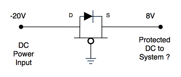
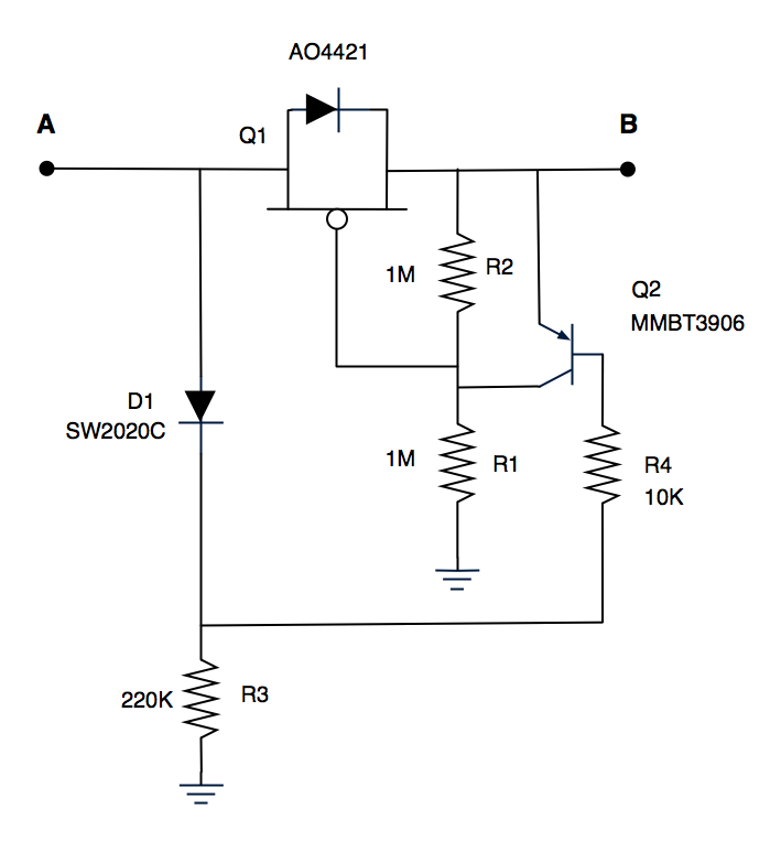
| 22:18, 24 April 2011 | PropB UVP.png (file) |  |
52 KB | Added diode part number | 2 |