XO DC Input Details
This page describes the XO DC Input circuit (requirements) in detail.
Introduction
The DC power input circuit on the XO laptop is unique. It is designed to accept a power from a wide range of input voltages (11 to 24V), protect itself from harm by a larger range of input voltages (-40 to 40V), and is also designed to seek the maximum power point of a solar input device.
Models
This is a description of the original DC input power circuit used in the XO-1.5 production models (C2/C3), as well as the new DC input power circuit introduced with the C4 production model.
The original DC power input circuit (based on a Fujitsu MB39A129) is almost identical to that used in the XO-1 laptops. The difference was the addition of software control over the input power limit in 1.5, allowing MPPT algorithms for solar power input. The input protection circuitry is the same.
Original Circuit
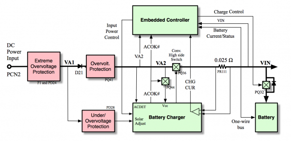
The original circuit provides the MPPT algorithm running on the Embedded Controller the following values:
- Input Voltage (VA2)
- Output Current from the battery charger, which is the sum of the system current and the battery current
- Output Voltage (VIN), equivalent to the battery voltage.
- Battery Voltage and Current, obtained via one-wire from the battery gas gauge
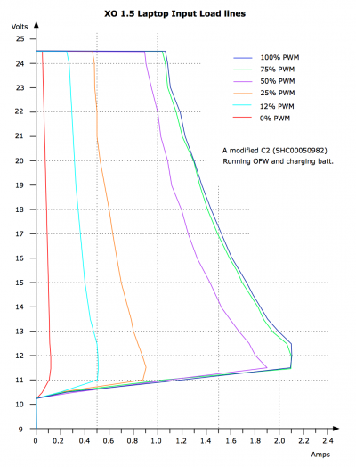
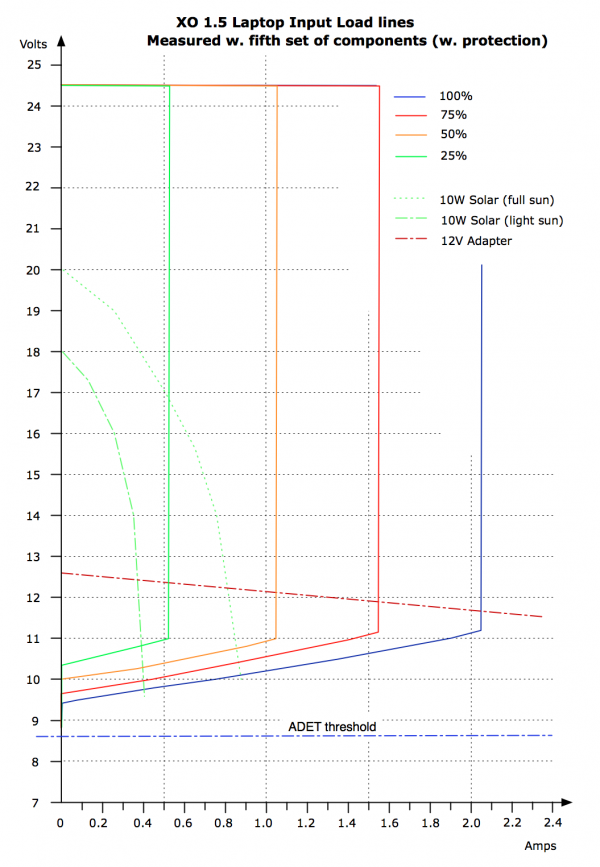
Hardware imposes a shape on the DC input impedance as shown in the following diagram. In particular, a maximum input power is specified (not a maximum input current) and the maximum input power decreases drastically as the input voltage drops below 11V.
The maximum input power may be modified under software control as shown by the 25%, 50%, and 75% curves. The precision varies but roughly 32 power steps are available.
Voltage Drop
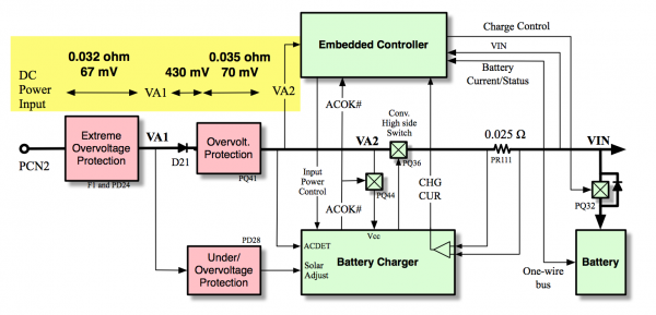
A critical flaw in the design was finally identified. The input voltage sensed by the EC is sensitive to the power drawn by the system --- up to 0.55 V of drop occurs as the input current increases from 0 to 2A !
New Circuit
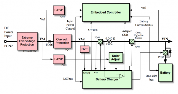
A new battery charger circuit was phased into production in the spring of 2011. This circuit provides the MPPT algorithm running on the Embedded_controller the following values:
- Input Voltage (VA1)
- Input Current to the battery charger
- Output Voltage (VIN), equivalent to the battery voltage.
- Battery Voltage and Current, obtained via one-wire from the battery gas gauge
The new battery charger (an Intersil ISL9519) requires additional circuitry to decrease the maximum input power as the input voltage drops below 11V. It was decided to attempt to control the maximum input power at higher input voltages through EC firmware. That is not shown in the following input impedance diagram:
