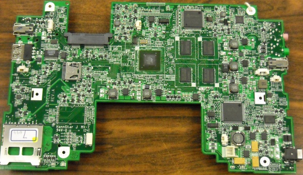
XO 1.75 A1
XO-1.75 Laptop Alpha test model, also known as A-test or A1.
Description
The A1 was the first prototype of the XO-1.75 built. The A1 bring up happened in late October 2010.
The number of boards obtained was small, and distribution was limited to hardware testing and OFW and Linux kernel driver development.
The A1 is now deprecated.
Identification
- Bare circuit board, no case or display
Photographs:
Software Support
- The current EC Firmware release is 0.1.6. No later release in the series supports the A1.
- The current OpenFirmware release is Q4A07. No later release in the Q4A series supports the A1. (XO-1.75 use Q4xxx OpenFirmware releases. These will not work on an XO-1 or XO-1.5. For the first time, Open Firmware and the EC firmware is separate.)
- The current Linux image is os2 http://build.laptop.org/F12-arm/os2/. os2 was the last image providing A1 support. No later image in the series supports A1.
It is strongly recommended that you have two sources of power (a charged battery and an external power source) when you upgrade your EC or OpenFirmware. Failure to do so may require the use of an SPI programmer to recover your laptop.
Upgrading the EC code
Using OpenFirmware on the host
- requires 0.1.5 or 0.1.6,
- requires Q4A07,
ok wifi name
ok flash-ec http:\\dev.laptop.org\pub\ec\cl2-0_1_6.img
Reading http:\\dev.laptop.org\pub\ec\cl2-0_1_6.img
Scan for: name found
Associate with: name
DHCP got 10.0.0.170
EC firmware verison: XO-EC 3 0.1.6 2010/12/08-19:06
Erasing ...

Writing ...
fff0
Verifying ...
fff0
Board powers down at this point due to EC restart. Power up manually.
Using SPI programmer
- not described
Using EC serial port
- not described
Upgrading OFW
Place a recent release of the Q4XYY firmware onto an SD device, and place it in the external SD slot.
Interrupt the OFW boot process by pressing the ESC key.
Type (assuming a q4a07 release):
flash ext:\q4a07.rom
Note: If upgrading from an unofficial Q4A04 release, the "int" and "ext" SD cards may be switched.
Reboot by holding down the power button once this is completed.
Using JTAG
If using JTAG to upgrade OFW, the CForth image begins at offset 0x2000 of the .rom file, and is of size 0x1e000. OFW is the rest of the .rom file, starting from offset 0x20000.
Upgrading Linux
Installing from OpenFirmware
You will need the .zd version of the OS image. Download it, then:
- Place the image on an SD card, and insert it into the XO-1.75 laptop's external SD slot.
- Get the Ok prompt,
- Install onto the internal SD card, type:
fs-update ext:\os1.zd
Installing from Linux using an XO-1.5
To install on an XO-1.5, boot an XO-1.5 to Linux, insert the SD card in the XO-1.5 external slot, then:
zcat os1.img.gz > /dev/mmcblk1
... and then power down, remove the SD card, and insert in the XO-1.75.
Installing from OpenFirmware using an XO-1.5
You will need the .zd version of the OS image. Download it, then:
- Place the image on a USB stick, and insert it into the XO-1.5 laptop's USB port.
- Get the Ok prompt,
- To install onto the internal SD card, type:
fs-update u:\os1.zd
To install an image onto the external SD card, you need to type:
devalias fsdisk ext:0
fs-update u:\os1.zd
... and then power down, remove the SD card, and insert it in the XO-1.75.
Restrictions
There is a list of recommended modifications (ECOs).
Despite the lack of any heat sink at this time, we haven't seen any overheating even in closed units.
Audio Inputs
The audio inputs are messed up. The internal microphone is wired to one channel, and one channel of the external microphone is wired to the other. Despite this, if the microphone is rewired the audio sounds pretty good (using Q4A05 or greater, type "test /audio").
Video Display
The video display is wired incorrectly, giving a pink hue to the video. It grows on you after a while...
There is no good "software cure" for this. At best, a complicated gamma table could minimize the wiring to completely fix the problem (using the unused LSB to contain the actual MSB, wiring it into place). The software team is lobbying for the bits to be manually shifted (6 wires, across pads that are 0.5mm apart!). While this is painful, it appears that it will be the accepted solution to "life through rosy lenses".
SD Flakiness
Versions of OFW up to Q4A05 operate the SD interfaces at 25 MHz unless it is told otherwise:
dev /sd false to avoid-high-speed? dend
Starting with Q4A05A (private release), operation of SD interfaces at 50 MHz is supported.
There are still some problems (#10457) on some motherboards.
USB
Still doesn't work (reliably/at all)
Documentation
Supporting documentation for these boards (all in PDF):
Please note that production boards will likely have different pin mappings and connector locations.
